The Build Diaries - Imperial Dalek


Project: Imperial Dalek
Date commenced:
Screen appearance:
Date completed:
Build Notes:
Head dome
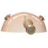
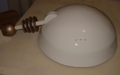 The head dome shown in the photo, is composed from several distinct parts, the head dome, the eye stalk and the dome lights (not shown in this photo – to see the lights, please seee below).
The dome is made from fibre glass. Whilst it's possible to make your own dome it's fairly involved. You need to begin by making arc shaped former, then use it to shape a huge blob of plaster. Once it has thoroughly dried and has been sanded it needs covering with release gel before creating a negative fibreglass mould. This mould is then used to create the required dome. I knew from information I’d read and conversations had with others, it wasn't always as easy as it sounds. Due to the work involved and the fact I had no fibre glass skills and you could buy a good one quite cheaply I decided it wasn’t worth creating a mould for it only to be used once given the amount of work involved.
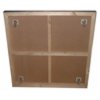
 After I'd read the plans I'd downloaded relating to dome movement, I drew a circle on a piece of wood small enough to fit inside the head dome in the required position. Into the circle I marked out four holes and the position of the eye stalk support. Once cut out it looked like the image. Before fixing it into your dome, it’s vital to ensure it is level and positioned correctly. This wooden circle is what the head dome will rotate on, if it wasn't level it would be as obvious as a badly fitted car tyre. I bolted it to the head dome circle with 4 x 40mm fixing angles bent to match the angle of the dome.
The mount for the eye stalk pivot was also fitted to this piece of wood prior to it being bolted to the dome, along with the mechanism to allow the eye stalk to tilt. This was comprised of two sections of tube to create a pulley as one piece of tube slid inside the other maintaining a vertical line and therefore a smooth rise and fall of the eye stalk. There was a lot of hidden complexity inside the head dome that nobody but the dalek operator will ever see.
Cutting the eye stalk slot in the dalek dome was not easy and was quite nerve racking, as I could only guess the minimum space required to be able to raise and lower the eye stalk. The eye stalk is surprisingly heavy and so the controls for raising and lowering it needed to be carefully adjusted and tested each time a change was made to ensure it was smooth and easy to use. The final step was to drill a hole in the centre of the wood, to allow it to be attached to the neck bin while spinning freely but maintaining a perfect circle with each rotation. Much later in the build, after the dalek had been painted the bolt holes were drilled into the dome to allow the lights to be attached.
The Eye stalk
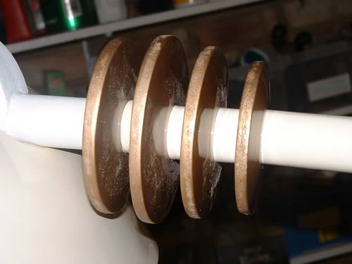
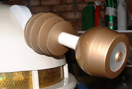 The eye stalk is made up of several specific parts. The eyeball, the focusing rings, the pivot which connects to the head dome and the shaft linking all the parts together.
The eyeball itself is made from a modified stainless-steel sugar bowl, with two discs of MDF carefully cut to size and fitted to the end, one on top of the other to create the different levels. Drilling the hole in the end of the bowl to it to the eye stalk was really difficult tricky as stainless steel is quite tough to drill through. The bottom was then rounded using car body filler which I sanded and refilled until I was happy with the circular shape.
The four focusing rings were made from four discs of MDF, each disc being padded on both sides with a smaller thinner disc of MDF the edges of which I painstakingly filled and sanded to create a smooth chamfered outline. Although it is quite prominent on the Dalek, it was a lot of work for what is essentially something that is largely overlooked. The added complexity is that each ring is a slightly different size and the second ring (counting away from the head dome) is the largest, while the fourth ring is the smallest. Whereas at first glance you may have expected the rings to be in descending size beginning with the first.
 The pivot was created from two offcuts of wood glued together, cut to size and sanded. Drilling the hole in the side of the pivot, into which the shaft would be embedded was delicate work. The diameter and position of the whole had to be pin point accurate to avoid breaking through the surface. A second hole was then drilled all the way through the centre of the first to allow a length of hollow threaded rod to pass through the pivot and provide the method to secure all parts of the head dome tightly together; a wobbly eye stalk was not an option I was prepared to entertain.
The cream coloured shaft shown in the photo was created from several lengths of plastic tube cut to size. It was then a matter of sanding the tube where required to ensure a tight fit as I threaded all the pieces of the eye stalk onto the threaded rod before bolting them together through the front of the eyeball. The use of hollow threaded rod was essential to allow wires to pass through the shaft of the eye stalk to illuminate the eyeball.
Dome Lights
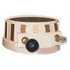
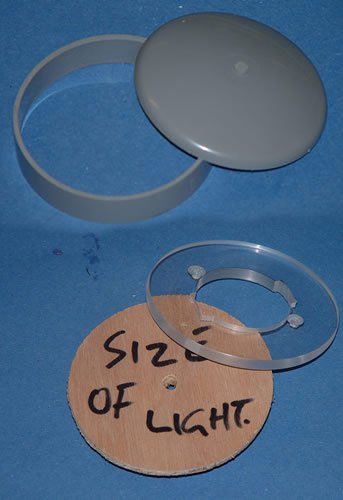 The lights were made from a piece of tube, a dished dome and a polished perspex ring. To create the dome lights, I began by carefully cutting two 20mm slices of tube with a hand saw and then lightly sanding any rough edges. An MDF ring with two holes and a larger opening in the centre to allow the wiring for the bulbs to be easily added was then fixed inside each ring. Two bolts were then threaded through the holes so I could anchor the finished light to the head dome. Cutting and polishing two 6mm Perspex rings ones one of the hardest, no, fiddliest jobs of the entire build. But I knew it was important they looked perfect as they’d be in most people’s eye line and imperfections would be obvious as they caught the light. Each perspex ring looked like a giant clear polo mint, these were then fixed to the MDF ring. To complete the light, they were topped with a dished dome bought from EMA model supplies.
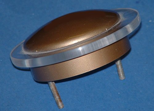 The last photo shown in this section is of a completed dome light, showing the bolts that are used to fix the light assembly to the head dome. The wiring for the lights was first attached to the head dome prior to the lights being fitted, the bulbs were pushed through the opening in the bottom of the dome light as it was lowered into position. If you’re reading this diary with a project of your own in mind, take care to ensure that is you use LED's of the correct voltage to suit your power supply or you risk blowing up your LEDs. Illuminating the lights was tricky. The light needed to be bright enough to be able to be seen. Originally Minty had a 12v/21w bulb in each light but these were switched to super bright white LEDs after my first event as I one of my domes melted due to the heat output of the lamps in a confined space.
Head
 I was very lucky to be able to purchase a well made
Cyber head, which needed a little more detail adding
to it to make it into the style of head featured in
Attack of the Cybermen.
I was very lucky to be able to purchase a well made
Cyber head, which needed a little more detail adding
to it to make it into the style of head featured in
Attack of the Cybermen.
After inspecting the head and comparing it to many
different photos, I began to add modifications and
finishing touches. First, I cut holes in the sides
of the head and added the fine mesh behind the
handles or Cyber ears. Inside the cyber head I also
added some detail to the top of the head and lastly
gave it a respray as it had been knocked about a
bit.
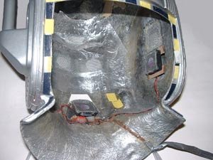
After wearing it for the first time in
warmer weather, it was modified to add a little air
circulation system. Inside the head I fitted three
small 40mm 12v fans. They provided just enough air
circulation, running from a 9v. In the photo you can
see two of the three fans, situated on the chin and
the sides. As a precaution all the wiring is sealed
so there’s no possibility of short circuit or a
minor shock due to dribble contacting the wiring.
The wires connect to a switch behind the chest unit,
so I can operate the fans without having to remove
the head each time.
The roof
It seemed logical to build the roof and light together as they needed to be part of the same section of the TARDIS build. Click here to skip down to the information about the TARDIS light.
The logical next step was the roof. This was the only part that I had a problem with. I incorrectly recorded one of my measurements and so calculated the wrong length of wood to cut. This was not too disastrous as I over allowed as opposed to under calculated my length.
 The roof was fun but tricky to make. I needed to
make a two square frames and then sit one on top of
the other. That would make the box on a box shape that
is so much a part of the TARDIS roof. I then had to
allow a slight slope up to the roof light platform. I
wanted it to be one piece but to be as light as
possible since I was going to have to lift it into
position, possibly on my own.
The roof was fun but tricky to make. I needed to
make a two square frames and then sit one on top of
the other. That would make the box on a box shape that
is so much a part of the TARDIS roof. I then had to
allow a slight slope up to the roof light platform. I
wanted it to be one piece but to be as light as
possible since I was going to have to lift it into
position, possibly on my own.
The build went really well, it was great fun assembling it all, like a giant model kit but having to machine all the parts in order to advance the build. I would say it was the most satisfying part to build since it was most tricky out of all the parts I had built up to that point. I then needed to sit the roof on something, in order to be able to locate it on top of the TARDIS.I designed a collar to fit on the top of the side panels that the roof could sit inside of. It also needed to blend into the TARDIS so you did not know how it was assembled from the outside. I removed the end caps from the top of the posts and used the mountings that they located onto as my fixing points. I decided to use the top part of the posts as markers to locate the roof inside and also stop it slipping out of position. This seemed to work well, however after two or three times of needing to disassemble the roof sections in the course of production it became obvious this was not a cunning plan and I screwed then both together. This was an excellent move as it greatly strengthened both parts and produced a roof section that was very strong and stable when being lifted into position.
Head
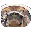
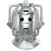
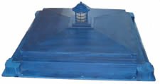
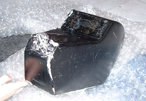 In many ways the head being made of moulded
fibreglass might have seemed like an incredibly easy
section of the prop to be completed. Far from it,
due to the amount of white putty that was embedded
into the fiberglass shell of the head led me to
suspect quite a lot of damage had been sustained to
the mould. All the white putty seen in the image
below needed to be painstakingly removed before the
sanding and repairs could be undertaken; it was a
lengthy process which I wouldn't want to repeat
anytime soon.
In many ways the head being made of moulded
fibreglass might have seemed like an incredibly easy
section of the prop to be completed. Far from it,
due to the amount of white putty that was embedded
into the fiberglass shell of the head led me to
suspect quite a lot of damage had been sustained to
the mould. All the white putty seen in the image
below needed to be painstakingly removed before the
sanding and repairs could be undertaken; it was a
lengthy process which I wouldn't want to repeat
anytime soon.
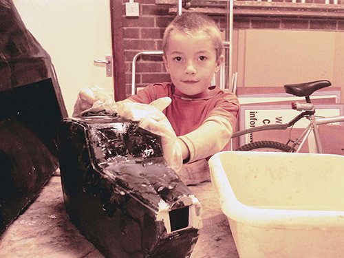 Once the holes had been filled sanded, and in some
cases refilled and sanded; work to create the head
could begin. The head needed a lot of sanding,
especially around the edges of the upper parts where
there's a lip to add more definition. The nose took
a lot of finessing to get it looking like the TV
prop as it'd sustained the most damage. The hole for
the nose gun was the first removed as I knew it'd
need careful filling and sanding to achieve the
overall effect I was looking for.
Once the holes had been filled sanded, and in some
cases refilled and sanded; work to create the head
could begin. The head needed a lot of sanding,
especially around the edges of the upper parts where
there's a lip to add more definition. The nose took
a lot of finessing to get it looking like the TV
prop as it'd sustained the most damage. The hole for
the nose gun was the first removed as I knew it'd
need careful filling and sanding to achieve the
overall effect I was looking for.
 Having consulted old clips of the show, photographs
and line drawings of the prop taken from a 1980s BBC
publication I knew this would be one of the most
complicated parts to complete. I needed to consider
things like what to make the nose gun from, how to
mount the ears, where to source the probe from, not
to mention the small matter of how to mount the head
onto the body. Written here it sounds easy but it
took several weeks to track down all the parts I
needed and to design a way to construct the neck
mounting so the head was removable. I knew it was
important to be able to remove the head because I
didn't want it to be damaged during transit.
Having consulted old clips of the show, photographs
and line drawings of the prop taken from a 1980s BBC
publication I knew this would be one of the most
complicated parts to complete. I needed to consider
things like what to make the nose gun from, how to
mount the ears, where to source the probe from, not
to mention the small matter of how to mount the head
onto the body. Written here it sounds easy but it
took several weeks to track down all the parts I
needed and to design a way to construct the neck
mounting so the head was removable. I knew it was
important to be able to remove the head because I
didn't want it to be damaged during transit.
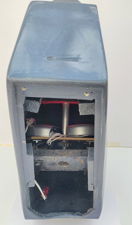 To allow the head to be removed and refitted, it
was necessary to create a removeable panel on the
bottom of the head. Any solution for fitting the
bottom panel needed to be light weight and allow
enough access to the inner parts of the head.
To allow the head to be removed and refitted, it
was necessary to create a removeable panel on the
bottom of the head. Any solution for fitting the
bottom panel needed to be light weight and allow
enough access to the inner parts of the head.
Having
cut a piece of wood the correct size and drilled a
hole in the centre for the neck mount I attached
some brackets using fiberglass resin and then
screwed it into position. The reason I couldn't
mount it directly to the head was maintaining access
to the probe and nose gun which would have been
obscured by the neck mount.
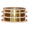
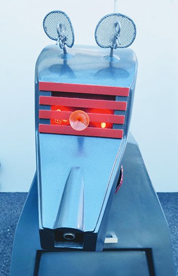
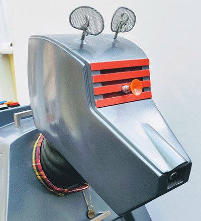 The horizontal red strips on the top of the head
were the thing I found most difficult to source
until I saw an advert for an ultra-thin cutting
board. The advert showed numerous colours including
red. Heading for a store I discovered it met all of
my requirements as I was keen to find something
which was thin, durable but consistently coloured
all the way through; rather than something which was
only coloured on the surface. Two cheap bike lights
provided the illumination the head required mounted
behind a small polycarbonate panel; while the probe
is an arrow taken from a kids bow and arrow set.
Both the nose gun and probe were created using short
length of aluminium tube of varying diameters set
inside each other. The centre of the nose gun was
then filled and painted black.
The horizontal red strips on the top of the head
were the thing I found most difficult to source
until I saw an advert for an ultra-thin cutting
board. The advert showed numerous colours including
red. Heading for a store I discovered it met all of
my requirements as I was keen to find something
which was thin, durable but consistently coloured
all the way through; rather than something which was
only coloured on the surface. Two cheap bike lights
provided the illumination the head required mounted
behind a small polycarbonate panel; while the probe
is an arrow taken from a kids bow and arrow set.
Both the nose gun and probe were created using short
length of aluminium tube of varying diameters set
inside each other. The centre of the nose gun was
then filled and painted black.